Electronic analog wristwatch comprising
a compass and an altimeter function
This invention relates to an electronic
analog compass device that can indicate different physical
measurement values using the technique of an ultrasonic motor.
Conventional compasses are mechanical compasses consisting of a compass
rose above which a free-moving compass needle is mounted on a pivot
indicating north. Electronic digital compasses were invented at a
later date. However, neither electronic analog compasses nor electronic
compasses which make use of the technique of a ceramic ultrasonic
motor have been invented to date. Even though this type of motor,
also known as electric piezo motor, is currently being used in numerous
applications (sonar, ultrasonic echo-sounding, echography, metallurgy,
process control in different fields) it has never been applied to
the movement of a compass needle.
Moreover, no compass to date has been designed which can indicate,
in addition to the direction of the magnetic north pole, the altitude
and the time with the same hands. There is no current mechanism that
allows three different measurements, i. e. the magnetic north pole,
the altitude and the time.
For indicating the magnetic north pole position and the time (hours
and minutes) with the same hands, magnetic interferences occur when
using quartz movements with a conventional motor, usually known as "Lavet" motor. "Lavet" motors
operate with permanent magnets and electric coils. The distortion
stray field caused by the permanent magnet has an influence on the
earth’s magnetic field. Therefore the resulting deviation has an
effect on the earth’s magnetic field as measured by the magnetic
field sensors of the compass. The consequential problem is that in
this case the sensors measure both the field resulting from the earth’s
magnetic field and the magnetic field generated by the "Lavet" motor.
Thus, the combination of a conventional quartz movement and an electronic
compass function in one unit is impossible without complex numerical
compensation.
Interferences result from the use of a conventional "Lavet" motor
created by the magnetic field generated by the permanent magnet of
the rotor. The invention has as its object to provide a solution
to the problems caused by these inferences. Ultrasonic motors do
not generate a disruptive magnetic field and therefore do not influence
the magnetic field sensors of a compass. Thus a compass comprising
of this type of motor can be used additionally and alternatively
as altimeter and watch and the measurement of the earth’s magnetic
field is possible without any problem. Ultrasonic motors generate
electric fields which do not influence the measurement of the earth’s
magnetic field.
The three functions of the compass (indication of the magnetic north
pole position, the time and the altitude) can coexist without causing
interferences.
The invention has as its object to create a compass using an ultrasonic
motor which was mainly developed by the CETEHOR group (France). This
compass is intended to allow the indication of the direction, the
measurement of time and the geographic altitude with one pair of
hands.
The advantage of this compass comprising an ultrasonic motor lies
in its ability to indicate at least three functions with one pair
of hands. This is made possible by the application of a ceramic piezo
motor in the object of the invention.
Firstly, the said ultrasonic motor is amagnetic therefore by definition
avoids inducing deviation of the magnetic field sensors of the compass.
As this motor (unlike the "Lavet" motor) does not generate a magnetic
field, it can neither interfere with nor neutralize the orientation
of the hands in the direction of the earth’s magnetic field.
Furthermore, an additional advantage of ultrasonic motors is that
they are bidirectional. This means that the hands can be moved in
two directions as is the case in conventional compasses and altimeters.
Since the piezo motor, in contrast to the conventional "Lavet" motor
which is usually one directional, operates in two directions (by
changing the frequency of heading) it is especially suitable for
the functioning of a compass and/or altimeter.
A further characteristic of the ultrasonic motor is that it can generate
great power at a low number of revolutions per minute and has a big
static torque.
This type of motor facilitates the precise final adjustment and setting
of the hands.
The hands can be driven directly without additional gears.
This specific characteristic makes the piezo motor extremely suitable
for the functioning of a compass and an altimeter. This is particularly
true for the final adjustment of the hands as it suppresses any kind
of vibration caused by the free play of the gears or the inertia
of the hand or the hands during the final adjustment. The hand or
the hands do not settle down slowly (as is the case in conventional
compasses or altimeters), but they indicate the determined final
value immediately.
Thus, by employing an ultrasonic motor in an electronic compass there
is no longer any friction created between the hand and the pivot
as is the case in conventional mechanical compasses. This represents
a great advantage for the final adjustment of the hand or the hands.
When the piezo motor is employed in the object of invention it facilitates
a rapid and precise indication. The electronic measuring and determination
of the earth’s magnetic field is realized immediately (within milliseconds)
and without any loss of precision (optimal precision).
The invention will now be described in detail, with reference to
the accompanying diagrams, in which:
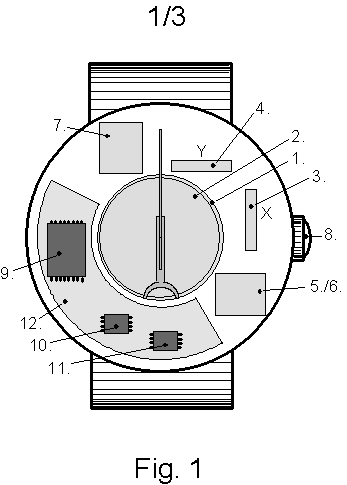
FIG. 1 is a view of the interior of the object of invention;
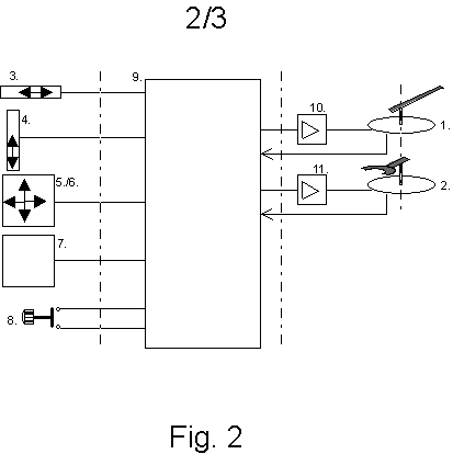
FIG. 2 is a schematic diagram (electric circuit diagram) of the use
of the piezo motor in the object of invention;
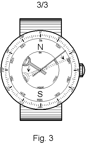
FIG. 3 is a view of the exterior of the object of invention with
an example of the measurement of the altitude and direction by the
compass.
With reference to these figures the illustrated device comprises
two piezo motors that are placed above each other with motor (1)
being connected to a long bidirectional hand indicating the minutes
and motor (2) being connected to a short bidirectional hand indicating
the hours of a time piece.
Two magnetic field sensors are arranged in such a way as to electronically
measure the earth’s magnetic field wherein sensor (3) generates the
vectorial signals required for measuring direction X and sensor (4)
generates the vectorial signals required for measuring direction
Y. The angle between the two sensors is 90°, so that the vectorial
addition of both sensor signals (3) and (4) in a right angled coordinate
system leads to the northern direction to be determined, provided
that the plane between direction X and Y is parallel to the horizontal
plane.
Moreover, the object of invention comprises two accelerator sensors
(5 and 6) in the same housing wherein one is required for indicating
direction X and the other for direction Y. These two sensors are
needed for measuring the earth’s acceleration which is indispensable
for the optimal and precise determination of the magnetic northern
direction as soon as the plane between direction X and Y is no longer
parallel to the horizontal plane. The measurement value provided
by these two accelerator sensors allows for the calculation of the
angle between the horizontal plane and the plane between direction
X and Y. This information serves to project the measured vector onto
the horizontal plane. Only the direction projected on the horizontal
plane corresponds precisely to the magnetic northern direction.
The object of invention also integrates a sensor that is sensitive
to atmospheric pressure (7) for determining the altitude.
A push-button is placed on the crown that can be operated by pressing
it down in order to select the desired modes of function and display
(compass for determining the magnetic northern direction, altimeter
for determining the altitude, time piece for determining the time)
while concurrently it facilitates the adjustment of the hands through
rotation.
The object of invention comprises a microcontroller (9) necessary
for the processing of the signals generated by the various sensors
(magnetic field sensor, accelerator sensor, atmospheric pressure
sensor). These signals are subsequently transmitted to the piezo
motor connected to the minute hand (1) via an amplifier (10) and
to the piezo motor connected to the hour hand (2) via a second amplifier
(11).
The finished object of invention comprises a printed circuit board
(12) on which the electronic components are soldered.
FIG. 2 is a view of the electric circuit diagram of the object of
invention.
The different sensors (the magnetic field sensors (3) and (4), the
accelerator sensors (5) and (6), the atmospheric pressure sensors
(7)) generate electric analog signals that, in a first phase, are
transformed into digital signals. This rapid digitalization of the
signals is followed by a second phase wherein at first the digitalized
information is linearized and then processed by a microcontroller
(9).
This microcontroller in turn produces information that, in a last
phase, is transmitted via amplifier (10) and (11) to the piezo motors
containing a closed loop regulation for the positioning of the hands.
The two piezo motors then transmit the calculated by the microcontroller
to the hands.
FIG. 3 is a view of the exterior of the object of invention. Referring
to this figure the illustrated device comprises a long bidirectional
hand for the indication of the minutes as well as a shorter, broader
hand for the indication of the hours (time piece function).
If the said compass is alternatively used as an altimeter, the smaller
of the two hands indicates a precise and final measuring of the altitude
in steps of 100 meters of altitude, while the other hand indicates
the altitude in steps of 1000 meters of altitude. The combination
of both hands results in a precise altitude reading. In the example
of FIG. 3 the altitude amounts to 5150m.
Alternatively both indicators facilitate the reading of direction
in degrees if they are used for the determination of the northern
direction. Then they are aligned on a single axis in such a way that
the angle between them amounts to 180°. In that position both hands
become one single hand and indicate one given direction. In the example
of FIG. 3 the compass is directed towards east north-east.
Claims
1. Electronic analog compass characterized in that each of its hands
is connected to a ceramic ultrasonic motor (known as electric piezo
motor).
2. Electronic analog compass according to claim 1 characterized in
that said compass includes one or several sensors or magnetic field
sensors for the electronic measurement of the earth’s magnetic field.
3. Electronic analog compass with electric piezo motor according
to claims 1 and 2 characterized in that said compass comprises one
or several accelerator sensors in order to measure the acceleration
of the earth for optimum indication of the North pole position.
4. Electronic analog compass with electric piezo motor according
to claims 1 to 3 characterized in that said compass includes one
or several amplifiers connected to a microcontroller as well as a
printed circuit board on which electronic components are soldered.
5. Electronic analog compass with electric piezo motor according
to claims 1 to 4 characterized in that said compass incorporates
an electronic analog altimeter.
6. Electronic analog compass with electric piezo motor incorporating
an electronic analog altimeter according to claim 5 characterized
in that the same pair of compass hands indicate both direction and
altitude.
7. Electronic analog compass with electric piezo motor incorporating
an electronic analog altimeter according to claims 5 and 6 characterized
in that said compass includes at least one atmospheric pressure sensor
in order to electronically measure the altitude.
8. Electronic analog compass with electric piezo motor incorporating
an electronic analog altimeter according to claims 1 to 7 characterized
in that said compass includes an electronic analog multifunction
timepiece usually in the form of a wristwatch.
9. Electronic analog compass with electric piezo motor incorporating
an electronic analog altimeter including an electronic analog multifunction
timepiece according to claim 8 characterized in that the same pair
of compass hands not only indicates direction and altitude but also
time and alarm time.
10. Electronic analog compass with electric piezo motor incorporating
an electronic analog altimeter including an electronic analog multifunction
timepiece according to claims 1 to 9 characterized in that said compass
comprises a push-button placed on the crown in order to select (by
pressing the push-button down) the desired display and to adjust
the position of hands by way of rotation.
SUMMARY
The electronic analog compass comprises an ultrasonic motor (also
known as electronic piezo motor) integrating an electronic analog
altimeter and an electronic analog multifunction timepiece usually
in the form of a wristwatch.
This invention relates to an electronic analog compass device using
the technique of an electronic piezo motor and thus, by way of the
same pair of compass hands, provides for the measuring of different
kinds of data (northern point of the compass, altitude and time).
The invention consists of two electronic piezo motors (1) and (2)
including a facility for detecting the position of the hands with
each motor being connected to a bidirectional hand. The invention
comprises two magnetic field sensors (3) and (4), two accelerator
sensors (5) and (6) as well as an atmospheric pressure sensor (7).
The electric signals generated by the sensors are digitalized, then
linearized and eventually processed by a microcontroller, which in
turn generates signals that are transmitted via the amplifiers (10)
and (11) to the motors. The amplifier (10) is connected to piezo
motor (1) and the amplifier (11) is connected to piezo motor (2).
In addition, the invention comprises a printed circuit board on which
the various electronic components are soldered. Furthermore, a push-button
placed on the crown of the compass allows the selection of the different
modes of functioning and display as well as the adjustment of the
hands. The invention is especially designed for sportsmen (e.g. divers),
for military purposes (in the field of topography) and for radio
amateurs.


